DADiSP Online Help
Click here to see this page in full context

DADiSP Worksheet Functions > Function Categories > Fourier Transforms and Signal Processing > KWLPASS
Designs an FIR linear phase Kaiser lowpass filter.
KWLPASS(order, rate, fc, fstop, attn, "unity_dc")
|
order |
- |
Optional. An integer, the filter length. If not specified, the filter order is automatically estimated. |
|
rate |
- |
A real, the sample rate of the filter in Hertz. |
|
fc |
- |
A real, the cutoff frequency in Hertz. |
|
fstop |
- |
A real, the stopband frequency in Hertz. |
|
attn |
- |
A real, the stopband attenuation in dB. |
|
"unity_dc" |
- |
Optional. A string, "unity_dc" explicitly sets f(0) to 1.0 |
A series, the lowpass filter coefficients. The filter coefficients are identical to the impulse response of the FIR filter.
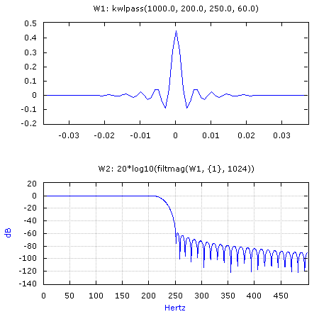
W1: kwlpass(1000.0, 200.0, 250.0, 60.0)
W2: 20*log10(filtmag(W1, {1}, 1024))

Generates a 75 point lowpass filter with a pass band edge of 200 Hz and a stop band edge of 250 Hz. The stopband attenuation is 60 dB and the time offset is -0.037 seconds. W2 displays the frequency response of the filter.
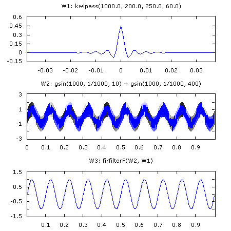
W1: kwlpass(1000.0, 200.0, 250.0, 60.0)
W2: gsin(1000, 1/1000, 10) + gsin(1000, 1/1000, 400)
W3: firfilterf(W2, W1)

Generates the same FIR lowpass filter as the previous example. W2 contains a series with two sinusoids and W3 applies the filter to recover the low frequency sinewave.
W2: kwlpass(90, 1000.0, 200.0, 250.0, 60.0)
Designs the same filter as above except the filter order is explicitly set to 90 samples resulting in a slightly narrower transition band.
W3: kwlpass(90, 1000.0, 200.0, 250.0, 60.0, "unity_dc")
Same as above except the DC frequency response value, f(0), is explicitly set to 1.0 (0.0 dB).
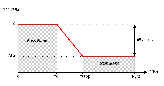
The KWLPASS filter specifications are depicted as follows:

KWLPASS designs a lowpass filter using a Kaiser window method. The impulse response of the ideal filter is multiplied by a Kaiser window to produce a linear phase FIR filter with a flat passband. The filter is non-causal and time symmetric about t = 0 and the offset is equal to:
- (length-1) / (rate * 2)
The filter order refers to the number of resulting filter coefficients.
The optional "unity_dc" flag guarantees the resulting filter has a frequency response of 1.0 (i.e. 0 dB) at f(0).
The lowpass edges must lie between 0.0 and 0.5 * rate (the Nyquist frequency). Overlapping band edges are not permitted.
Although a filter designed with the Kaiser window method exhibits a flat passband response, the resulting filter generally has more coefficients than the Remez Exchange method. See LOWPASS to design a linear phase FIR lowpass filter using the Remez Exchange algorithm.
See BESSEL, BUTTERWORTH, CHEBY1, CHEBY2 and ELLIPTIC to design IIR filters using the Bilinear Transform method.
KWLPASS requires the DADiSP/Filters Module.
Oppenheim and Schafer
Discrete Time Signal Processing
Prentice Hall, 1989
Digital Signal Processing Committee
Programs for Digital Signal Processing
I.E.E.E. Press, 1979
Bateman & Yates
Digital Signal Processing Design
Computer Science Press, 1989