
DADiSP Online Help
Click here to see this page in full context

DADiSP Worksheet Functions > Function Categories > Fourier Transforms and Signal Processing > BESSEL
Designs a digital IIR Bessel filter.
|
BESSEL( |
type, order, rate, pb1, pb2, ripple, attn, sb1, sb2, "options") |
|
type |
- |
An integer, the filter type.
|
||||||||||
|
order |
- |
Optional. An integer, the filter length. If not specified or set to -1, the filter order is automatically estimated. |
||||||||||
|
rate |
- |
A real, the sample rate of the filter in Hertz. |
||||||||||
|
pb1 |
- |
A real, the first passband edge in Hertz. |
||||||||||
|
pb2 |
- |
A real, the second passband edge in Hertz. |
||||||||||
|
ripple |
- |
Optional. A real, the passband ripple in dB. Defaults to 3 dB. |
||||||||||
|
attn |
- |
Optional. A real, the stopband attenuation in dB. Defaults to 40 dB. |
||||||||||
|
sb1 |
- |
Optional. A real, the first stopband edge frequency in Hertz. Defaults to |
||||||||||
|
sb2 |
- |
Optional. A real, the second stopband edge frequency in Hertz. Defaults to |
||||||||||
|
"options" |
- |
Optional. A string, zero or more filter options:
|
A series, the Bessel filter coefficients in multi-stage cascade format.
W1: bessel(1, 1000.0, 100.0)
W2: 20*log10(filtmag(W1, 1024));sety(-80, 10)
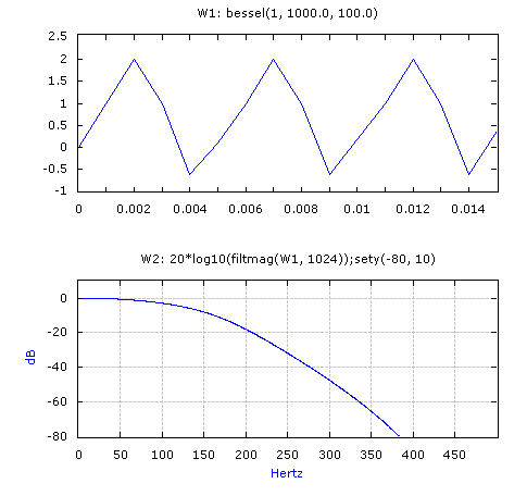
W1 creates a Bessel lowpass filter with a sample rate of 1000 Hz and a cutoff frequency of 100 Hz. Although the stopband frequency defaults to 150 Hz, the actual stopband frequency is constrained by the filter order and cutoff frequency. W2 displays the frequency response of the resulting filter.
W1: bessel(1, 1000.0, 100.0, 3.0, 50.0, 130.0)
W2: gsin(1000, 1/1000, 3) + gsin(1000, 1/1000, 250)
W3: iirfilter(W2, W1)
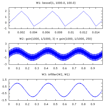
Creates the same IIR lowpass filter as the previous example. W2 contains a series with two sinusoids and W3 applies the filter to recover the lower frequency sinewave.
W3: bessel(3, 8, 1000.0, 200.0, 300.0)
Creates a Bessel bandpass filter with a sample rate of 1000 Hz, a filter order of 8 and a passband that extends from 200 Hz to 300 Hz. The resulting number of coefficients is 41.
W1: bessel(1, 1000.0, 100.0, "analog")
W2: 20*log10(filtmag(W1, 1024, "analog"));semilogx;sety(-80, 10)
Same as the first example, except the result is an analog filter. The rate parameter is ignored.
W1: bessel(3, 11, 1000.0, 200.0, 300.0, "norm_phase")
W2: 20*log10(filtmag(W1, 1024));sety(-100, 10)
W3: butter(3, 11, 1000.0, 200.0, 300.0)
W4: 20*log10(filtmag(W3, 1024));overp(w2, lred);sety(-100, 10)
W1 contains an 11th order Bessel bandpass filter with a passband from 200 to 300 Hz. The filter is normalized with the "norm_phase" option.
W2 displays the frequency response of the Bessel filter.
W3 contains an 11th order Butterworth bandpass filter with a passband from 200 to 300 Hz.
W4 displays the frequency response of the Butterworth filter. The Bessel filter is overplotted for visual inspection indicating the Bessel filter asymptotes conform to the Butterworth filter.
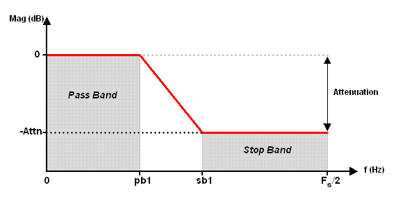
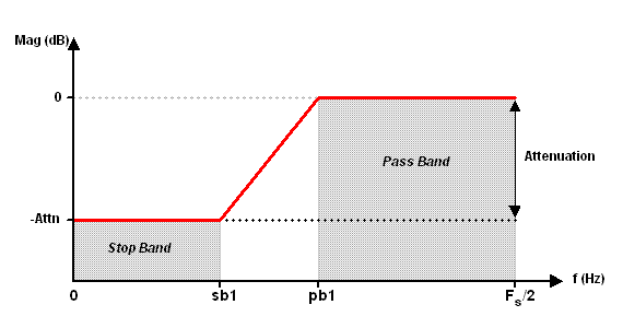
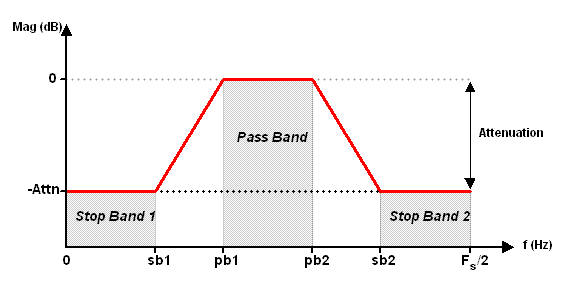
The generic BESSEL filter specifications are depicted as follows:
Type = 1, Lowpass
Type = 2, Highpass
Type = 3, Bandpass
Type = 4, Bandstop
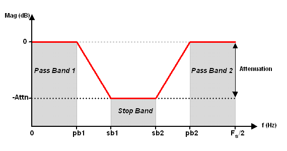
For filter type 1 and 2 (lowpass and highpass), the band frequencies pb2 and sb2 are omitted.
BESSEL uses the Bilinear Transform Method to compute the coefficients by converting an analog filter prototype to the digital domain. Unlike other IIR filter types, the resulting specifications are constrained by the filter order and the filter response may not meet the desired specifications.
If "matched_z" is specified, the matched z transform is used instead of the BILINEAR transform. The matched z transform maps the analog prototype filter poles and zeros to the digital domain with:
z = e sT where T is the sample rate of the digital filter.
To best preserve the linear phase characteristics of a Bessel filter, the "matched_z" option is suggested. However, the resulting filter response should be verified since the matched z transform can alter the filter specifications. Because an analog Bessel filter is an all pole realization, the matched z transform is identical to the impulse invariant transform.
The filter order refers to the number of resulting poles (2X poles result for type 3 and type 4) and is not equivalent to the number of filter coefficients.
The band edges must lie between 0.0 and 0.5 * rate (the Nyquist frequency). Overlapping band edges are not permitted.
The filter coefficients are produced in multi-stage bi-quad form suitable for processing by the CASCADE function.
The cascade stages are ordered such that the poles of each stage are closer to the unit circle than the previous stage. The zeros of each stage are chosen to be closest to the poles of the same stage.
If "analog" is specified, the filter coefficients represent an analog filter, with coefficients in cascaded second order stages of analog frequency s. In this case, the rate parameter is ignored.
The transfer function of an analog low pass Bessel filter with a cut off frequency of ωc is given by the all pole expression:

where n is the filter order and the reverse Bessel polynomial is defined as:

with

The poles can be normalized to modify the characteristics of the Bessel filter response.
|
"norm_mag" |
Normalizes the poles such that the -3 dB magnitude response occurs at pb1. The -3 dB frequency remains fixed for increasing filter order. This is the default normalization, also referred to as frequency normalization. |
|
"norm_phase" |
Normalizes the poles such that the unwrapped phase response reaches half the maximum phase shift at pb1. For a given filter order, the maximum phase shift is |
|
"norm_delay" |
Preserves the natural Bessel polynomial coefficients such that the phase response for increasing filter order remains fixed at -1 radians at pb1. For pb1 normalized to 1.0, the group delay at 1.0 is 1. The resulting -3 dB cut off frequency increases for increasing order. |
A Bessel filter exhibits approximate linear phase characteristics for an IIR filter. Use a FIR filter to generate a digital filter with exactly linear phase at the expense of more filter coefficients.
BESSEL supports Bessel filters to a maximum order of 25.
Bessel filters are also referred to as Bessel-Thomson filters.
See BANDPASS, BANDSTOP, HIGHPASS and LOWPASS to design linear phase FIR filters using the Remez Exchange method.
See BESSELJ to evaluate the Bessel function.
BESSEL requires the DADiSP/Filters Module.
Oppenheim and Schafer
Discrete Time Signal Processing
Prentice Hall, 1989
Digital Signal Processing Committee
Programs for Digital Signal Processing
I.E.E.E. Press, 1979
Bateman & Yates
Digital Signal Processing Design
Computer Science Press, 1989