DADiSP Online Help
Click here to see this page in full context

DADiSP Worksheet Functions > Function Categories > Fourier Transforms and Signal Processing > HIGHPASS
Designs an FIR linear phase highpass filter.
HIGHPASS(order, rate, fc, ripple, attn, fstop)
|
order |
- |
Optional. An integer, the filter length. If not specified, the filter order is automatically estimated. |
|
rate |
- |
A real, the sample rate of the filter in Hertz. |
|
fc |
- |
A real, the cutoff frequency in Hertz. |
|
ripple |
- |
Optional. A real, the passband ripple in dB. Defaults to 3 dB. |
|
attn |
- |
Optional. A real, the stopband attenuation in dB. Defaults to 40 dB. |
|
fstop |
- |
Optional. A real, the stopband frequency in Hertz. Defaults to |
A series, the highpass filter coefficients. The filter coefficients are identical to the impulse response of the FIR filter.
W1: highpass(1000.0,100.0)
W1 creates an FIR highpass filter with a sample rate of 1000 Hz and a cutoff frequency of 100 Hz. The stopband frequency defaults to 50 Hz. The resulting filter is 25 samples long with a passband ripple of 1.8 dB and a stopband attenuation of 52 dB.
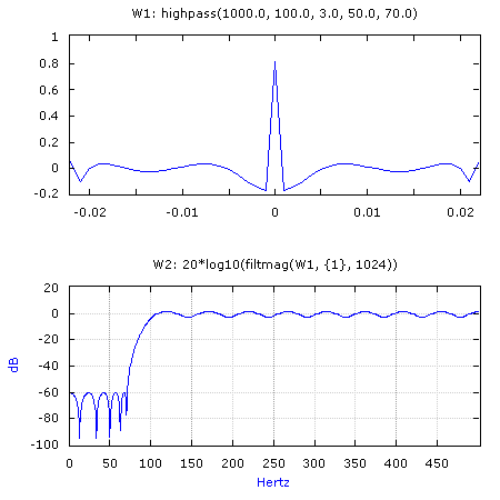
W1: highpass(1000.0, 100.0, 3.0, 50.0, 70.0)
W2: 20*log10(filtmag(W1, {1}, 1024))

Creates a similar filter except the desired stopband attenuation is set to 50 dB and the stopband frequency is increased to 70 Hz. The resulting filter contains 45 samples with a passband ripple of 2.27 dB and the stopband attenuation increases to 60 dB. W2 displays the frequency response of the filter.
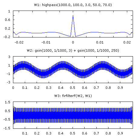
W1: highpass(1000.0, 100.0, 3.0, 50.0, 70.0)
W2: gsin(1000, 1/1000, 3) + gsin(1000, 1/1000, 250)
W3: firfilterF(W2, W1)

Creates the same FIR highpass filter as the previous example. W2 contains a series with two sinusoids and W3 applies the filter to recover the higher frequency sinewave.
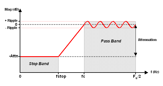
The HIGHPASS filter specifications are depicted as follows:

HIGHPASS uses the Remez Exchange algorithm to compute the FIR filter coefficients. The Remez Exchange algorithm will attempt to meet or exceed the filter specifications with a linear phase FIR filter.
The filter order refers to the number of resulting filter coefficients, though the order will always be odd for a highpass filter.
The highpass edges must lie between 0.0 and 0.5 * rate (the Nyquist frequency). Overlapping band edges are not permitted.
See KWHPASS to design a linear phase FIR highpass filter with a flat passband using the Kaiser Window method.
See BESSEL, BUTTERWORTH, CHEBY1, CHEBY2 and ELLIPTIC to design IIR filters using the Bilinear Transform method.
HIGHPASS requires the DADiSP/Filters Module.
Oppenheim and Schafer
Digital Signal Processing
Prentice Hall, 1975
Digital Signal Processing Committee
Programs for Digital Signal Processing
I.E.E.E. Press, 1979