DADiSP Online Help
Click here to see this page in full context

DADiSP Worksheet Functions > Function Categories > Fourier Transforms and Signal Processing > ZPFCOEF
Designs a digital filter from a set of analog (s domain) zeros and poles.
ZPFCOEF(Z, P, K, Fs, Fp)
|
Z |
- |
A series consisting of the zeros of the analog filter transfer function in Hertz. |
|
P |
- |
A series consisting of the poles of the analog filter transfer function in Hertz. |
|
K |
- |
Optional. A real, the filter gain. Defaults to 1.0. |
|
Fs |
- |
Optional. A real, the sample rate of the digital filter. Defaults to 1.0. |
|
Fp |
- |
Optional. An integer, the warping frequency. The magnitude to the digital filter at Fp matches the magnitude of the analog filter, defaults to Fs. |
A series. The coefficients of the digital filter in cascade form.
f := 0..1..10000
w := 2*pi*f
s := i*w
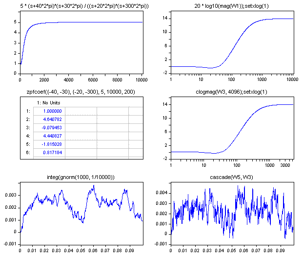
W1: 5 * (s+40*2*pi)*(s+30*2*pi) / ((s+20*2*pi)*(s+300*2*pi))
W2: 20 * log10(mag(W1));setxlog(1)
W3: zpfcoef({-40, -30}, {-20, -300}, 5, 10000, 200)
W4: clogmag(W3, 4096);setxlog(1)
W5: integ(gnorm(1000, 1/10000))
W6: cascade(W5, W3)

W1 contains the original S domain transfer function.

The magnitude of the transfer function is displayed in W2. The zeros of the transfer function for
W3 contains the resulting digital filter coefficients in 2nd order cascade form. The sample rate of the digital filter is 10000 Hz and the response is set to match the analog filter at 200 Hz. The Z domain transfer function is:

The entire frequency response of the digital filter is displayed in W4.
W5 contains synthesized data and W5 filters the data with the resulting digital filter in W3.
The digital filter conversion is performed using the bilinear transform. The CASCADE format is used for speed and accuracy in the digital filtering process.
The cascade coefficients represent the product of 2nd order stages in the following syntax:

The cascade coefficients are saved in the following order:

The number of poles must equal or exceed the number of zeros.